The various phases involved in a study using TATAMI
1? Creation of a study / Loading a plan
| The user adjusts the general characteristics of the study, loads a plan background (.dwg for example) and the size. | 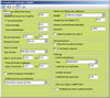 See pictures See pictures |
2? Definition of the structure of the floors
| The user checks the data relating to the floors. The default values proposed are parameterisable and can be modified. Tatami manages all the layout systems (A, B or C as defined in standard EN 1264) and can also handle customised floor structures. | 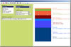 See pictures See pictures |
3? Definition of the rooms
| The user now defines the rooms and zones to be fitted with pipes. As the user draws, Tatami automatically calculates all the dimensions. This is Visual mode's major strength. | 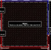 See pictures See pictures |
4? Placement of the manifolds/Associating the rooms
| The user places the manifolds and draws the connections to the rooms. Tatami automatically analyses these connections (the rooms passed through, the length), and simultaneously carries out all the relevant calculations (the layout interval, number of circuits, lengths, etc.), providing unrivalled working comfort. | 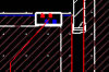 See pictures See pictures |
5? Circuits management
| The user then defines his circuits zones by taking advantage of the numerous possibilities offered by the software. Tatami then automatically generates the circuits, without any further intervention being required. | 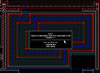 See pictures See pictures |
6? Around the manifold
| Thanks to the features offered by Tatami, the user designs the area immediately around the manifolds at his convenience (adjusting the connections, allocating the manifold's lanes, etc.). | 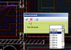 See pictures See pictures |
7? Costing
| As the study has now been finished, the user can generate the costing without any trouble at all... | 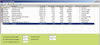 See pictures See pictures |
8? Print-out
| ... And print out the results in clear, good-quality documents. | 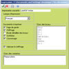 See pictures See pictures |